The PAVL User Manual
Platform Overview
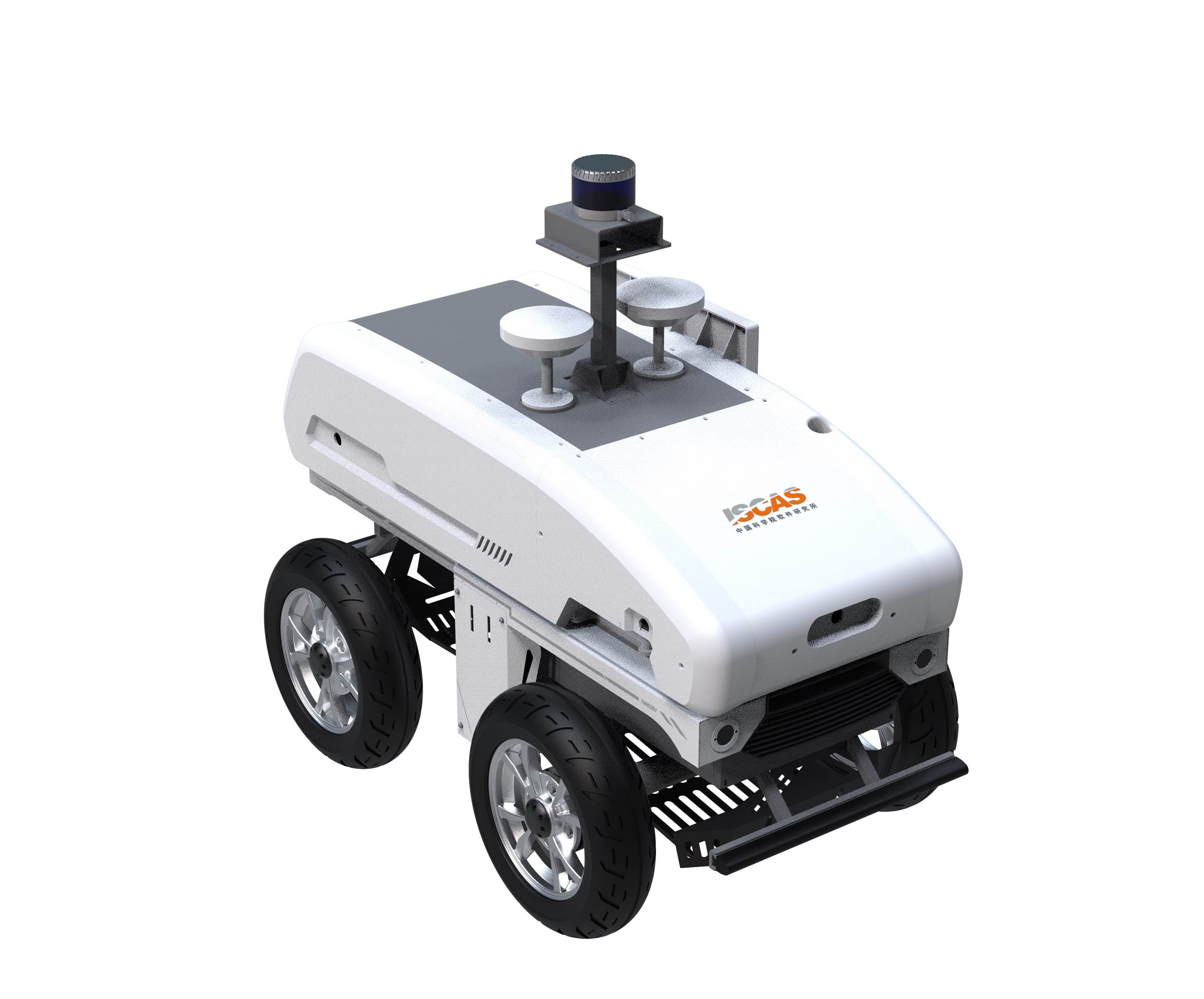
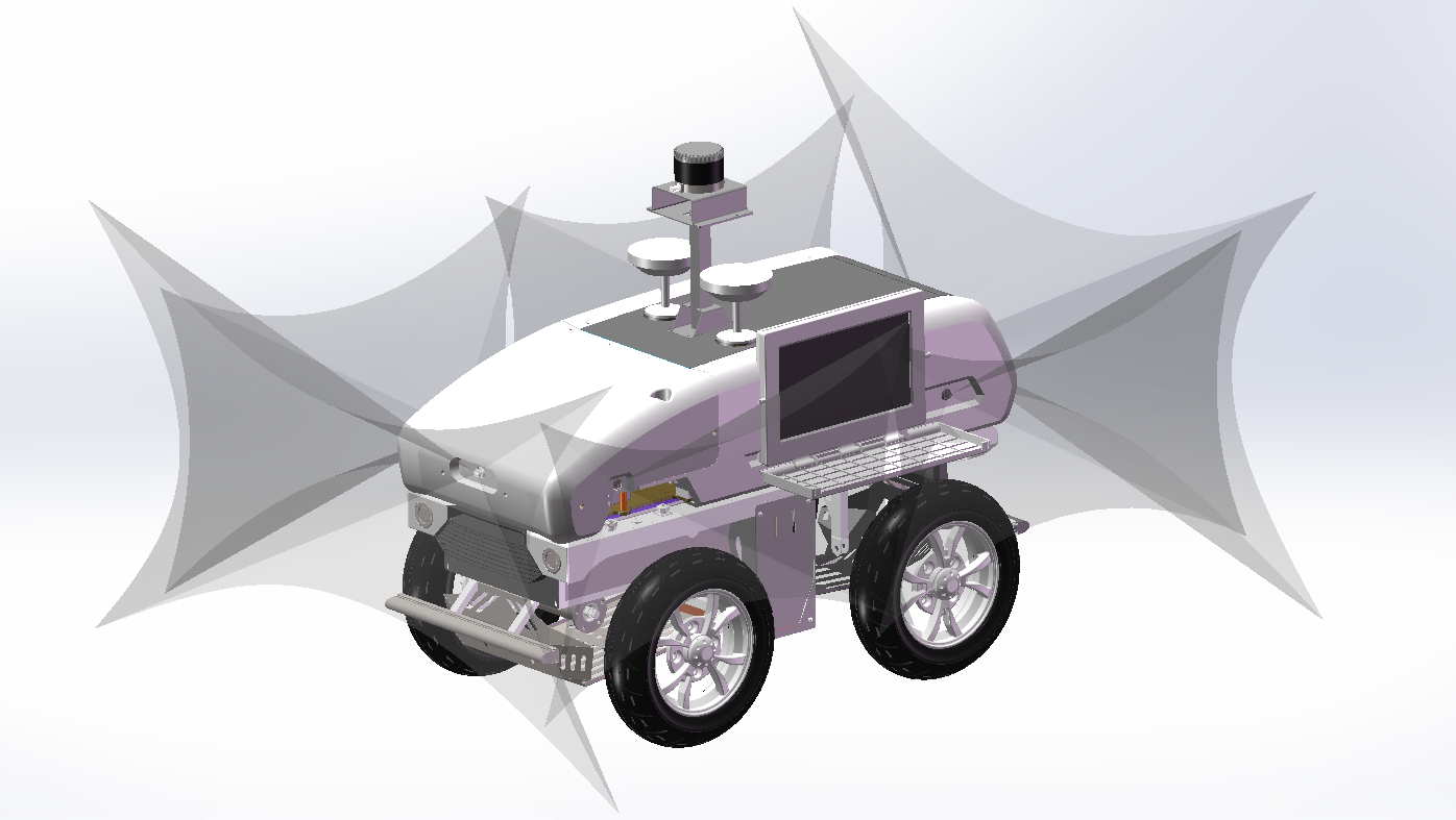
PAVL stands for Physical Agents Vehicle Large. It is a modular and integrated unmanned vehicle experimental system combining hardware, software, and algorithms, designed to support the development, testing, and validation of various autonomous driving technologies.

System Components
| Module | Primary Function | Supported Components/Features |
|---|---|---|
| Chassis module | Motion control | Sensor connection interface, control module connection |
| Hardware control | Sensor integration | HD cameras, depth cameras, radar, GPS, IMU |
| Algorithm module | Intelligent decision-making and control | SLAM, autonomous navigation, UniAD framework, neural network control algorithms, deep learning optimization |

PAVL Configuration
Chassis
- Prerequisites for chassis startup
- Ubuntu 16/Ubuntu 18 system
- ROS1 installed on Ubuntu
- Check CAN status
- Connect the CAN card to the USB port of the computer.
- Open a terminal and enter the command
lsusbIf the output includes the following, the CAN card is functional. If not, set the DIP switch on the CAN card to 2 down, 1 up (“down” is ON).
Device 030: ID 1d50:606f OpenMoko, Inc.
- Boot settings
- Check if there is an
rc.localfile under the/etc/directory. If not, copy it using the following command:sudo cp rc.local /etcIf
rc.localexists, add the following content above theexit 0line and save:sleep 2 sudo ip link set can0 type can bitrate 500000 sudo ip link set can0 up - Ensure the CAN card is connected to the USB port of the industrial PC before booting or restarting.
- If the RX and TX lights are on, the setup is successful.
- Check if there is an
- Immediate setup
- After re-plugging the CAN card, execute the following commands to enable it:
sudo ip link set can0 type can bitrate 500000 sudo ip link set can0 up - The RX and TX lights should turn on, indicating a successful setup.
- After re-plugging the CAN card, execute the following commands to enable it:
- Communication test
- Connect the CAN cable from the chassis to the CAN card: the red wire from the chassis connects to CANH, and the black wire connects to CANL.
- If the blue receiving light on the CAN card flashes, the connection is correct. Otherwise, check if the chassis is powered on and the CAN cables are connected correctly. (Ensure direct connection of the chassis’s CAN cable to the CAN card before adding an extension cable.)
- Install can-utils (
sudo apt-get install can-utils). Open a terminal and entercandump can0to view the data received by the CAN card from the chassis.
- Compilation
- Open a terminal and navigate to the
yhs_fr07_oc_prodirectory. - Compile using the following command and wait for completion:
catkin_make
- Open a terminal and navigate to the
- Execution
- Open a terminal, navigate to the
yhs_fr07_oc_prodirectory, and enter the following commands:source devel/setup.bash roslaunch yhs_can_control yhs_can_control.launch - If the output includes:
>>open can device success!then the device is successfully opened.
- Open a terminal, navigate to the
- Testing
- Before testing, ensure the vehicle is lifted, or set the chassis speed to a very low value.
- Open a terminal, navigate to the
yhs_fr07_oc_prodirectory, and enter the following commands:source devel/setup.bash rostopic echo /ctrl_fbIf feedback data refreshes continuously, the ROS driver package is functioning normally.
- Send commands to control chassis movement:
- Open a terminal, navigate to the yhs_fr07_oc_pro directory, and enter:
source devel/setup.bash - Enter the following command but do not press
Enteryet:rostopic pub -r 100 /ctrl_cmdAfter auto-completing the rest of the command with the
Tabkey, provide gear, speed, and steering angle values (note: angles should be in degrees, not radians). PressEnterand switch the remote controller to auto mode. If the red and blue lights on the CAN card flash, the chassis will start moving.
- Open a terminal, navigate to the yhs_fr07_oc_pro directory, and enter:
Hardware Configuration and Initialization
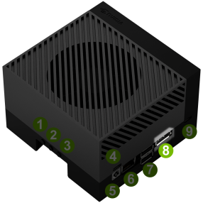
Setting up the Jetson AGX Orin 64G Compute Board
- Initial setup with display connection
- Connect the following peripherals to the development kit:
- DisplayPort cable: Connect to a computer monitor. (If using an HDMI-input monitor, use an active DisplayPort-to-HDMI adapter/cable.)

- USB keyboard and mouse.
- Ethernet cable (optional if planning to connect to the internet via WLAN).
- DisplayPort cable: Connect to a computer monitor. (If using an HDMI-input monitor, use an active DisplayPort-to-HDMI adapter/cable.)
- Connect the supplied power adapter to the USB Type-C™ port above the DC jack.
- The development kit should automatically power on. A white LED near the power button will light up. If not, press the power button.
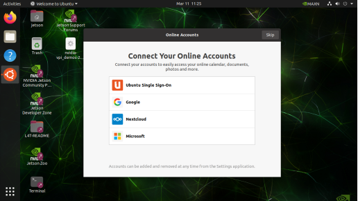
- Wait approximately one minute until the Ubuntu screen appears on the monitor.
- During the first boot, the development kit will guide you through the following setup steps:
- Review and accept the NVIDIA Jetson Software EULA.
- Select system language, keyboard layout, and time zone.
- Create a username, password, and computer name.
- Configure wireless network settings.
- Once the
oem-configprocess is complete, the development kit will reboot and display the Ubuntu desktop.
- Connect the following peripherals to the development kit:
- Installing the JetPack components
- After completing the initial setup, install the latest JetPack components corresponding to your L4T version from the Internet. Open the Ubuntu desktop and press
Ctrl + Alt + Tto open a terminal. - Check your L4T version using the following command:
cat /etc/nv_tegra_releaseIf the output resembles the following:
# R34 (release), REVISION: 1.0, GCID: 30102743, BOARD: t186ref, EABI: aarch64, DATE: Wed Apr 6 19:11:41 UTC 2022This indicates you have L4T suitable for JetPack 5.0 Developer Preview.
- If the L4T version is earlier, manually configure the apt repository entries:
sudo bash -c 'echo "deb https://repo.download.nvidia.com/jetson/common r34.1 main" >> /etc/apt/sources.list.d/nvidia-l4t-apt-source.list' sudo bash -c 'echo "deb https://repo.download.nvidia.com/jetson/t234 r34.1 main" >> /etc/apt/sources.list.d/nvidia-l4t-apt-source.list' - If the L4T version is
R34.1or newer, install JetPack components using the following commands:sudo apt update sudo apt dist-upgrade sudo reboot sudo apt install nvidia-jetpackThe installation may take about an hour, depending on your internet speed.
- After completing the initial setup, install the latest JetPack components corresponding to your L4T version from the Internet. Open the Ubuntu desktop and press
Configuring the Sensing Intelligent HD Camera
Official documentation and driver packages are available in the appendix.
-
Copy and extract the driver package: copy the compressed package to the Jetson AGX Orin Devkit and extract it to the default path (
/home/<username>/SG8A-ORIN-GMSL). -
Connect the lens: connect the compatible lens to the adapter board at the CAMx position (x corresponds to CAM0-CAM7 ports).
- Load the drivers: open a terminal, navigate to
/home/<username>/SG8A-ORIN-GMSL, and execute the following script:./quick_bring_up.shThen follow the prompts to update the system drivers, load the drivers, and activate the lens.
- Install the utilities: install the
v4l-utiltool:sudo apt install v4l-utils
Updating or changing the camera model for the first time requires a system reboot.
Usage example
- Run the script: follow the prompts to select the corresponding port and camera model.
- Interactive example: the script will display the following:
Please select your camera type:
2 # Enter the camera type number.
Please select your camera port [0-7]:
1 # Enter the corresponding adapter board port number.
Start bring up camera!
Precautions
- Camera parameter issues: if the selected camera parameters are incorrect, restart the service using the following command:
sudo systemctl restart nvargus-daemon- Camera plugging and unplugging: when plugging or unplugging a camera, unload the corresponding camera driver file before rerunning the script.
- GMSL2F suffix cameras: these cameras (e.g.,
SG3-ISX031C-GMSL2F) only support activation on CAM1, CAM3, CAM5, and CAM7.- Repeated driver loading: if the driver is already loaded, the script may produce the following error, which can be ignored:
insmod: ERROR: could not insert module sgx-yuv-gmsl2.ko: File exists
Configuring the Radar
After successfully compiling the lslidar_c16 package (driver source code linked in the appendix), follow these steps to operate the radar:
- Start the driver and decoder nodes: in a terminal, navigate to the workspace and launch the radar using:
roslaunch lslidar_c16_decoder lslidar_c16.launch --screenThis launch file starts both the driver and decoder, which are necessary to operate the radar.
- Verify the parameters: to change the radar configuration (e.g., target IP, port, or rotation speed), edit the
lslidar_c16.launchfile. Default settings include:- Device IP
- Port: 2368
- Rotation Speed: 10Hz
Modify the relevant parameters and save the changes.
- Test data reception: check the status of the data reception using:
rostopic listthe following topics provide different levels of radar data:
/lslidar_packet_c16: raw lidar packet data for analysis and decoding./lslidar_packet_difop_c16: configuration data packets with radar parameters, status, and rotation speed./lslidar_point_cloud: decoded point cloud data for 3D modeling or visualization./scan: 2D scan plane data for applications like SLAM and obstacle avoidance./rosout: this is the standard logging output topic in the ROS system. It records logs from all nodes and is used for system monitoring and debugging./rosout_agg: this is the aggregated logging output topic, which consolidates all log messages from/rosoutfor centralized viewing./scan: this is the scan data from LiDAR, with a type ofsensor_msgs/LaserScan. Each message contains complete 2D scan plane data, suitable for applications that use laser scan data format, particularly for SLAM and obstacle avoidance in 2D environments.
These topics provide data at different levels:
/lslidar_point_cloudand/scanare processed data, ready for use in environment modeling, path planning, or visualization;/lslidar_packet_c16and/lslidar_packet_difop_c16provide raw data packets and device configuration information, used for low-level decoding and driver configuration.
Appendix
- Reference Materials:
- NVIDIA Official Documentation: Get Started with Jetson AGX Orin Devkit
- LiDAR Driver Source Code: GitHub - lslidar_c16
- Camera Documentation and Drivers:
- Feishu: Documentation
- GitHub: Drivers